Pipeline transportation has become the primary mode of energy transport in modern times, and the resulting development of pipeline valves has been rapid, greatly promoting the progress of pipeline transportation. How exactly are pipeline valves defined, and what are the differences in their structure, characteristics, and performance? Today, let’s take a closer look at the unique features of pipeline valves.
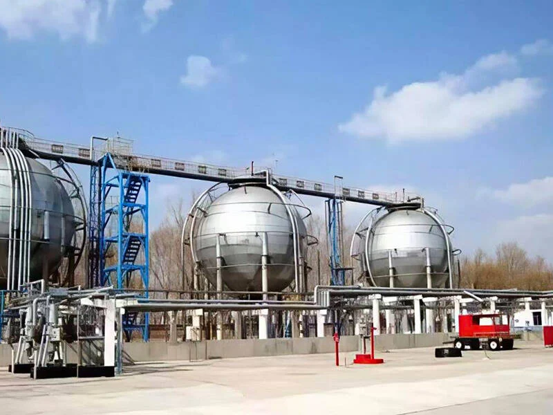
Pipeline transportation has become the primary mode of energy transport in modern times. Utilizing long-distance pipelines to transport resources such as oil, gas, and coal has become the most important means of solving energy transportation problems in the world today.
Major oil and gas producing and consuming countries around the world extensively use long-distance pipelines to solve the problem of transporting oil and gas resources. More than 95% of natural gas transportation is carried out via pipelines.
Development History
In 1914, the first 9-kilometer-long oil pipeline was built in the central United States, thus beginning the development of the pipeline industry. The cost of transporting liquids or gases via pipelines is one-third that of rail transport and two-thirds that of sea transport, so it has experienced rapid development in the last hundred years.
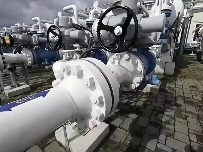
Long-distance pipelines are called long-distance pipelines, and the valves used on these pipelines are called pipeline valves. These include ball valves, gate valves, check valves, and plug valves. They are specialized valves with specific functions to meet the special requirements of pipeline transportation.
Structure and Characteristics of Pipeline Valves
(1) Flat Gate Valve
Structure: A flat gate valve is a sliding valve with a parallel gate as its closing element. The closing element can be a single gate or a double gate with a spreading mechanism. The pressure of the gate against the valve seat is controlled by the medium pressure acting on the floating gate or floating valve seat. If it is a double-gate flat gate valve, the spreading mechanism between the two gates can supplement this pressure.
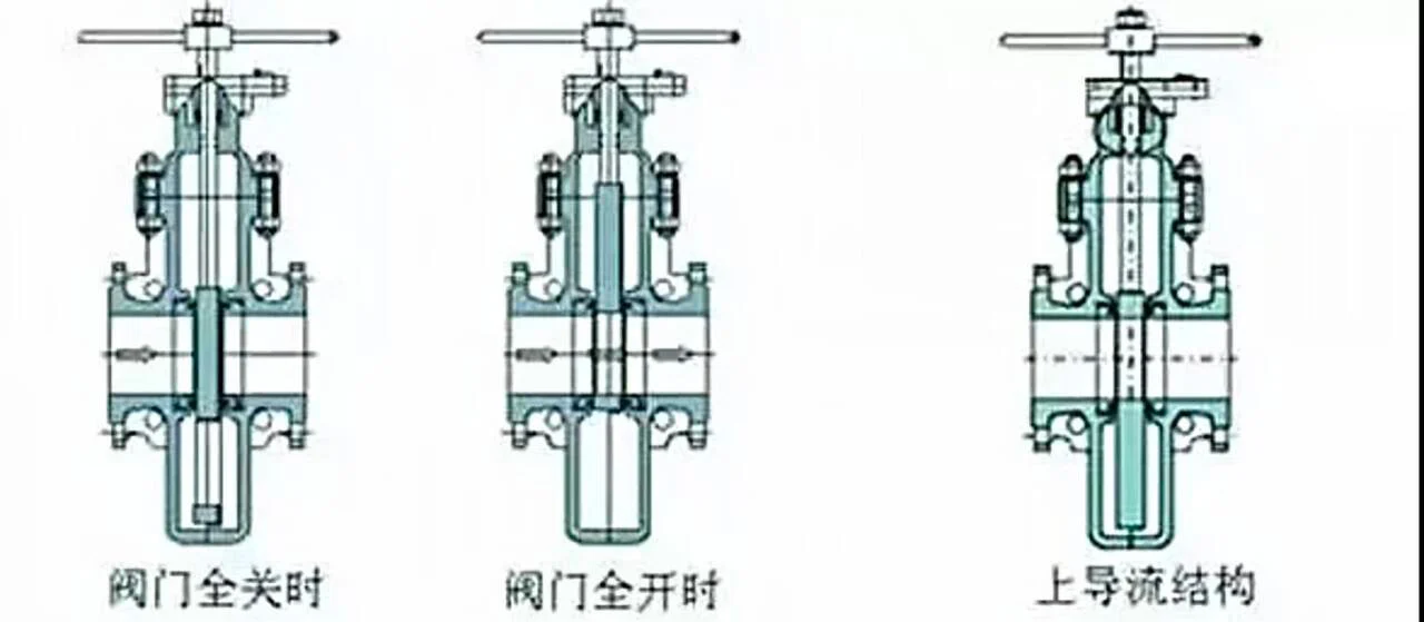
Characteristics: The main characteristics of a flat gate valve are: short structural length, good sealing performance, small operating torque and relatively close opening and closing forces, low flow resistance, and the valve does not need to be equipped with an abnormal pressure-boosting device. Flat gate valves with guide holes can be cleaned by a cleaner. However, the valve’s structural height is high, approximately 3 to 4 times the pipe diameter.
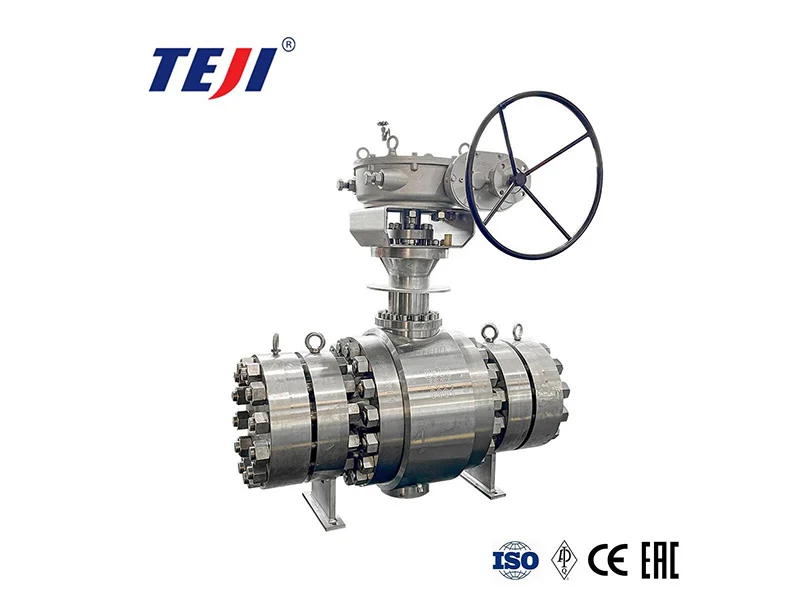
Structure: A ball valve is a valve that uses a ball with a circular through-hole as the opening and closing element. The ball rotates with the valve stem to achieve the opening and closing action. The opening and closing element (ball) is driven by the valve stem and rotates around the axis of the square ball valve.
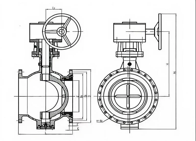
Features: Compact structure, good sealing performance, 90° rotation for rapid opening and closing, short operation time, secondary auxiliary sealing can be formed by injecting sealing grease, fireproof valve seat can ensure valve sealing in case of fire, and a quick shut-off device can realize emergency opening and closing of the valve.
(3) Spherical Control Valve
Structure: A spherical control valve includes a left valve body, valve seat, ball, valve stem shaft, and right valve seat. Its characteristic is that a circular channel penetrating the center of the ball is provided perpendicularly to the original flow channel hole. A butterfly plate is placed in the channel, one end of which has a protrusion that mates with a groove at one end of the valve stem shaft, and the other end is limited by a limiting ring.
Features: Spherical control valves have a large flow rate, simple structure, good stability, convenient operation and maintenance, low flow resistance when fully open, allow for a large differential pressure, low noise, and good anti-cavitation performance.
Structure: Check valves all have an opening pressure. When the working medium pressure is greater than the check valve opening pressure, the spring is compressed, the check valve baffle is pushed open, and the medium flows smoothly. When the working medium flows back, the medium will press the baffle against the check valve body. The greater the medium pressure, the tighter the pressure. At this time, the baffle completely isolates the entire system, eliminating the possibility of medium backflow. The structure of the check valve can be understood more intuitively.
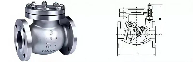
Features: Check valves often have a damping structure, which can effectively eliminate pipeline vibration and reduce flow resistance; they adopt double sealing (elastic sealing for low pressure and metal-metal sealing for high pressure), with good sealing effect; they can be passed through pipeline cleaners.
(5) Pressure Relief Valve
Structure: Pressure relief valves mainly have two types of structures: spring type and lever type. Spring-loaded valves rely on the force of a spring to seal the valve disc against the valve seat. Lever-loaded valves rely on the force of a lever and a counterweight. With the increasing demand for large-capacity valves, a pulse-type pressure relief valve, also known as a pilot-operated pressure relief valve, has emerged, consisting of a main pressure relief valve and an auxiliary valve. When the pressure of the medium in the pipeline exceeds the specified pressure value, the auxiliary valve opens first, allowing the medium to flow along the conduit into the main pressure relief valve, which then opens the main pressure relief valve, reducing the increased medium pressure.
Features: Starting or stopping the pump may cause changes in the flow velocity and pressure fluctuations in the pipeline, generating shock waves. To eliminate the impact of shock waves, pressure relief valves are used on long-distance pipelines to mitigate them.
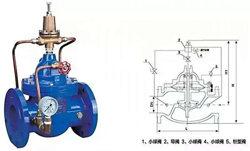
(6) Pressure Reducing Valve
Structure: The pressure reducing valve (200X type, adjustable pressure reducing valve) allows the outlet pressure to be set via a valve spring. When water is supplied from the inlet, the water flows through the needle valve into the main valve control chamber, and the outlet pressure acts on the pilot valve through the conduit. When the outlet pressure exceeds the pilot valve spring setting value, the pilot valve closes. When drainage in the control room stops, the pressure inside the main valve control room increases and closes the main valve, preventing further pressure increases at the outlet. When the valve outlet pressure drops to the pilot valve spring set pressure, the pilot valve opens, and the control room drains downstream.
Features: Pressure reducing valves are installed on branch pipelines to maintain a constant medium pressure at the user’s inlet. Pilot-operated pressure reducing valves are commonly used, offering less susceptibility to medium cleanliness, higher pressure control accuracy, and stable performance.
Technical Requirements
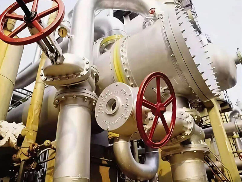
Long-distance pipelines are global, serving as energy supply lines, stretching from the Arctic Circle to the equator, from mountains to the seabed, from plateaus to deserts, traversing earthquake zones, swamps, permafrost, rivers, lakes, and hillsides. Some are erected overhead, others buried underground, operating in the field, making maintenance difficult, and requiring a 30-year service life. They typically transport crude oil and natural gas, which, although processed, contain sulfur, rust, and metal particles, requiring a zero-level seal. The harsh operating environment and the importance of the energy supply line place stringent technical requirements on pipeline valves.
So, what are the specific technical requirements for pipeline valves?
Strength and Toughness: In addition to withstanding the internal medium pressure, valves must withstand the bearing capacity of the foundation, axial tensile and compressive forces caused by changes in ambient temperature, and external loads caused by landslides, ground subsidence, and floods. In cold and frozen regions, the low-temperature impact toughness of the material must also be considered to prevent low-temperature brittle fracture. For fully welded ball valves, the fracture toughness (CTOD) of the weld seams and heat-affected zone needs to be considered according to fracture mechanics theory.
Zero-Class Sealing Requirements: Valves require a zero-class seal to ensure effective cutoff of downstream pipelines. The influence of metal particles in the medium on the zero-class seal must be considered. Metal-to-metal seals serve as the primary seal, PTFE/rubber-to-metal seals as the secondary seal, and emergency sealing measures should be taken in case of seal failure. 3. Pipeline ball valves with fire safety and anti-static functions must be designed with fire safety in mind. In the event of a fire, the external and internal leakage of the valve must not exceed the leakage standards specified in API 607. The ball, held in place by a non-metallic material, may generate static electricity and must be conductive to the valve body. At 24VDC, the resistance should be <10 ohms.
DBB function: During valve cavity drainage, both the upstream and downstream valve seats should automatically shut off simultaneously to ensure safe drainage.
Prevention of valve cavity pressure trapping: Regardless of whether the valve is open or closed, the medium should be prevented from being trapped in the valve cavity. If trapping is possible, automatic pressure relief must be ensured for both gaseous and liquid media. The maximum pressure relief should not exceed 1.33 times the valve’s rated pressure. The external pressure relief valve should have a diameter of DN15 or larger.
Drainage: The medium in the valve cavity can be drained; online sealing testing of the valve can be performed through this drain port.
Position Indication: Whether manually or power-driven, the valve position indicator must clearly show whether the valve is in the open or closed position.
Drive Chain: The design torque of the drive chain should be at least twice the maximum torque of the ball valve.
Sulfurized Pressure-Bearing Components and Bolts: The materials should be resistant to stress cracking and meet NACE, MR0175 requirements.
Emergency Shutdown Function: For long-distance pipeline systems using a SCADA system, the valve should automatically shut off when the pipeline pressure drop rate or duration reaches a certain set value.
Consideration of Groundwater Potential Corrosion and Stress Corrosion: A fully welded valve body structure, cathode grounding of the pipeline, and external surface anti-corrosion measures are used to prevent potential corrosion and stress corrosion.