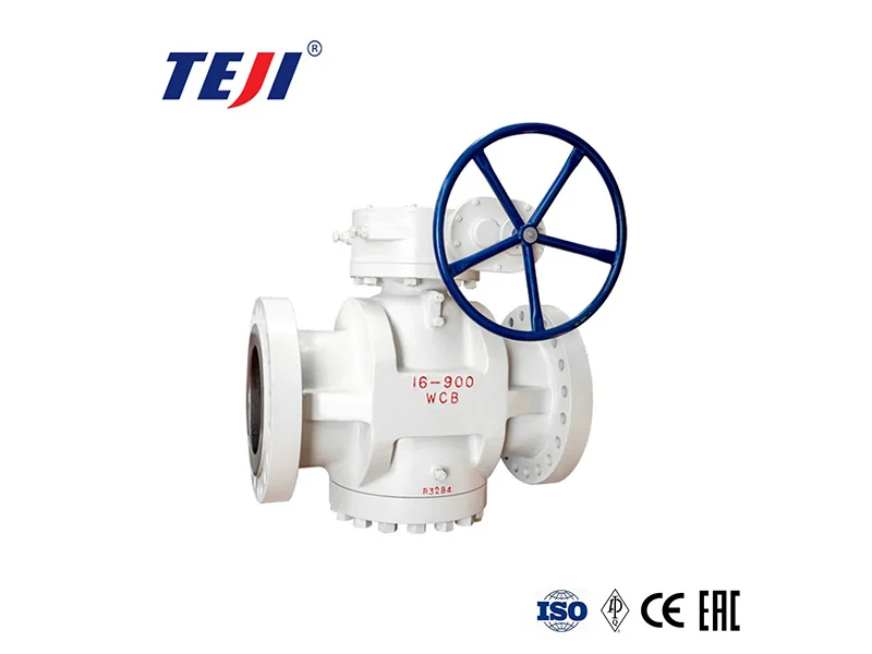
Metal-seated triple offset butterfly valves are valve components used for on/off control and flow control in pipeline systems. They are mainly used in petroleum, chemical, metallurgical, hydropower, and urban heating industries. They can be used in industrial pipelines with a medium temperature ≤425℃ for regulating flow and cutting off fluid.
Structural Features
The metal-sealed triple-eccentric butterfly valve employs a triple-eccentric design, where the valve stem axis is offset from both the butterfly plate center and the body center. The valve seat rotation axis and the valve body channel axis form an angular sealing structure. This structure includes three eccentric designs: the axis offset from the valve seat centerline, the axis offset from the pipeline centerline, and the valve seat cone tilt. The valve seat sealing ring is typically composed of a soft T-shaped sealing ring and multiple layers of stainless steel sheets. The valve plate sealing surface is overlaid with a corrosion-resistant alloy to form a slanted conical structure.
Advantages
The sealing characteristics combine the advantages of hard and soft metal seals, offering erosion resistance, wear resistance, frictionless opening and closing, and zero leakage. The sealing surface pressure is proportional to the medium pressure, providing high pressure resistance (PN10 – PN160) and high temperature resistance (-196℃ – 850℃). It can achieve adaptive sealing under bidirectional medium pressure (forward and reverse flow), meeting the requirements of high-temperature and high-pressure operating conditions.
Installation Instructions
Installing a metal-sealed triple-eccentric butterfly valve differs significantly from installing a standard centerline butterfly valve. Due to its multi-layered eccentric design (axial eccentricity, sealing surface eccentricity, and plate eccentricity) to achieve zero leakage and long service life, strict requirements are placed on the installation location, stress conditions, and cleanliness.
Pre-installation Inspection and Preparation
Parameter Verification: Confirm the valve’s nominal diameter (DN), pressure rating (PN/Class), applicable temperature, and material to ensure they fully match the pipeline conditions (medium, temperature, pressure).
Visual Inspection: Inspect the valve body and flange faces for any damage caused during transportation. Check that the valve stem rotates freely without jamming.
Flow Direction Confirmation: During installation, ensure the arrow direction aligns with the pipeline medium flow direction.
Pipeline Cleaning: Remove weld slag, rust, mud, and other impurities from the pipe flange faces and inner walls.
Lifting and Positioning
Important:Never use the actuator as a lifting point: Never use an electric/pneumatic actuator as a lifting lug to lift the valve. Use the lifting lugs on the valve body itself.
Maintain Disc Position:Before installation, manually open the disc approximately 5°~10% (slightly open).
Align Flanges:Gently place the valve between the two pipe flanges, ensuring the bolt holes are aligned. Do not allow the valve to bear the weight of the pipeline.
Bolt Tightening
Symmetrical Cross Tightening: Bolts must be tightened evenly in multiple stages using a diagonal sequence (cross-hatching method).
Single-sided Tightening is Strictly Prohibited: Tightening one side’s bolts first will cause immense stress, directly leading to valve body deformation or damage to the valve seat sealing surface.
Torque Control: Tighten according to the torque value specified in the flange standard; do not overtighten. For large-diameter valves, a torque wrench is recommended.
Gasket Selection: Ordinary rubber gaskets are strictly prohibited (they will carbonize and fail at high temperatures). Metal spiral wound gaskets, toothed gaskets, or metal ring gaskets should be selected according to temperature and pressure.
Installation Angle and Position
Horizontal Pipe Installation: Valve stem vertically upward (90°) or horizontally (0°).
Vertical Pipe Installation: Suitable for applications where the medium flows from bottom to top.
Space Allowance: Ensure sufficient space around the valve to allow the actuator to complete a 90° rotation, and also facilitate future maintenance and disassembly.
Actuator Wiring and Commissioning (Electric/Pneumatic)
Manual Test: After installation, do not power on. Manually operate the actuator to check if the valve opens and closes smoothly and without obstruction.
Jog Phase Calibration (Electric): Before the first power-on, manually place the valve in the half-open position. Jog the power supply and observe if the pointer or valve position indicator direction matches the actual valve movement. If opposite, immediately disconnect the power and reverse the power phase sequence.
Limit Adjustment: Triple eccentric butterfly valves typically do not require excessive pressure on the sealing surface for sealing. The stroke is pre-adjusted at the factory and generally does not require adjustment of the limit screws unless there are special stroke requirements.
Signal Calibration: For regulating valves, the linear relationship between the input signal (4-20mA) and the valve opening needs to be calibrated.
Special Operating Conditions and Precautions
High Temperature Conditions: If the medium temperature is very high, it is recommended to use a long-neck bonnet design, or install the valve on the side of a horizontal pipe section (to avoid bottom sedimentation) to protect the actuator and stuffing box.
Large Diameter Valves: For extra-large diameter valves, pipe supports must be installed, and the valve must never be subjected to load. Thermal expansion and contraction stresses in the pipeline must not be applied to the valve; otherwise, flange leakage or valve body deformation may occur.
By following the steps above, your triple offset butterfly valve should be installed correctly and safely. If you encounter interference between the butterfly plate and the flange during installation, please remove the valve first and do not force it. If necessary, please contact an expert.