Liu Zhi
(TEJI VALVE GROUP CO.,LTD. , Wenzhou 32500)
Abstract: This paper introduces an ultra-low temperature valve test device. The test device has the dual functions of low-temperature test liquid medium recovery and helium gas pressurization recovery for leak detection, so that the test liquid medium and gas medium can be recycled, energy saving and environmental protection, and the test cost is greatly reduced.
Key words: ultra low temperature; Liquid nitrogen; Helium recovery; Experimental device
1.Introduction
Common ultra-low temperature valves include ultra-low temperature ball valves, gate valves, globe valves, check valves, butterfly valves, and control valves. These valves are mainly used in ethylene and liquefied natural gas plants, air separation units, petrochemical tail gas separation equipment, cryogenic storage tanks and tankers for liquid oxygen, liquid nitrogen, liquid argon and carbon dioxide, as well as pressure swing adsorption oxygen production systems. The output liquid ultra-low temperature media, such as ethylene, liquid oxygen, liquid hydrogen, liquefied natural gas plants and liquefied petroleum products, are not only flammable and explosive but also vaporize and expand hundreds of times in volume when heated, which can easily lead to leaks and explosions. Given the characteristics of these media and the operational requirements of valves under ultra-low temperature conditions, the design, manufacturing, testing and installation methods of ultra-low temperature valves differ significantly from those of conventional valves. However, high-performance ultra-low temperature valve test equipment is currently lacking in the market for evaluating the performance of such valves. Additionally, ultra-low temperature test media and gases are expensive, resulting in high testing costs. Conventional valve test equipment uses inexpensive liquid media like water and gases for testing, without considering cost or external leakage safety issues. Therefore, testing with conventional valve test equipment would incur extremely high costs and fail to ensure production safety.
2.Existing Test Equipment
2.1.Ambient Temperature Test Equipment
Existing ambient temperature test equipment primarily operates on hydraulic principles, using liquid as the working medium and following Pascal’s principle to transfer energy. This converts the hydraulic force into clamping force to secure the valve on the pressure testing machine. The same principle is then applied to introduce the test medium (typically water) into the valve cavity through high-pressure pipes, enabling the execution of various required tests.
2.2 Existing Low Temperature Test Equipment
The existing common low temperature valve test equipment is shown in Figure 1,which mainly consists of a helium cylinder, pressure gauge, pipelines, test tank, auxiliary insulated box cover, temperature recording system and instruments, as well as terminal detection components such as bubble leak testing. The test procedures are as follows: Install the valve in the container and connect all joints, ensuring the valve packing gland is mounted at the upper part of the container where no vaporized gas is present. Before placing the valve into the liquid nitrogen tank, position temperature-measuring thermocouples at the following locations: the valve body (external), the ball or valve inner cavity, and the bonnet (stuffing box and packing area).After fixing the valve together with the test fixture, immerse the entire assembly into the cryogenic tank filled with liquid nitrogen, ensuring the liquid nitrogen covers the upper end of the valve body-bonnet connection. Wait until the liquid surface boiling ceases and stabilizes, and the valve cools down to -196℃.Then use the thermocouples to measure and record the temperatures of the valve body, ball and bonnet. Once the temperature meets the test requirements, introduce helium gas into one end of the valve in stages according to relevant specifications. After stabilizing the pressure at the outlet end within the specified time, detect the corresponding leakage rate. After passing the test, remove the valve and allow it to naturally return to room temperature.
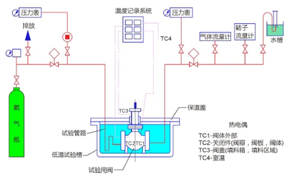
Shortcomings are as follows:1.The tested valve lacks a reasonable fixed position in the test tank, causing it to shake during valve operation, which makes it difficult to apply external force.2.The terminal leak detection device adopts the most primitive water displacement method, where the start and end points of both timing and water displacement are manually controlled, resulting in low accuracy and large errors in the final test results.3.After the test is completed, the helium gas is directly discharged into the atmosphere, leading to significant resource waste.
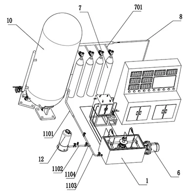
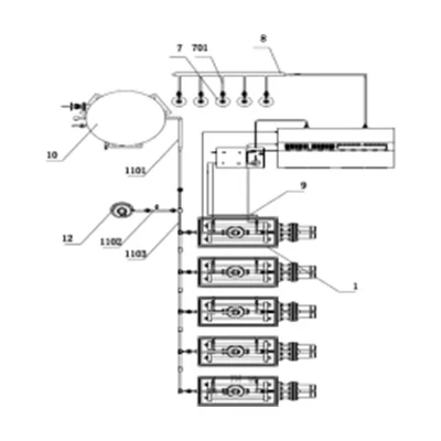
3.Novel Ultra-Low Temperature Valve Test Equipment
This equipment is shown in Figure 2(single channel test)and Figure 3(multi channel parallel test).Its main components include:liquid nitrogen storage tank,helium cylinder group,helium pipeline, multifunctional operating device,mobile portable control console,test tank box and auxiliary devices, as well as liquid nitrogen recovery and helium recovery devices.
In this set of equipment, liquid nitrogen is mainly stored in vertical tanks as the refrigerant medium. The liquid filling port of the storage tank adopts a standard quick-connect interface, facilitating liquid filling from tank trucks. To avoid insufficient helium pressure during testing, we have set up an independent helium bank, which allows multiple helium cylinders to apply pressure simultaneously according to actual needs. Before testing, similar to the existing low temperature test equipment, the valve under test is first fixed in the corresponding tank box using a special fixture. To prevent the valve from shaking during opening and closing, a customized multi-purpose fixing fixture is used: the valve is installed inside the fixture, and then the fixture is hoisted into the tank box. Positioning screws are installed at the four corners of the fixture’s upper surface. When these screws are screwed out to press tightly against the inner walls around the tank box, the fixture will not shake due to the peripheral constraints during valve operation, allowing the valve to be easily opened and closed under external force.
Secondly,to improve test accuracy,we have integrated two sets of testing methods into the helium leak detection device.We retain and upgrade the traditional water displacement method by incorporating a PLC timer into the drainage system:when the pressure source reaches the graduated cylinder and water drainage begins,the timer starts synchronously;similarly,when the pressure source is removed at the end of the test,the timer stops synchronously.The instantaneous leakage rate can be obtained through simple calculation.In addition,we connect a pressure sensor to the leak detection outlet,linking it to the operation console,so that the instantaneous leakage rate is directly displayed on the screen,completely eliminating manual operation.
To avoid wasting expensive helium after testing,we have added a helium recovery device to this test system,which serves a dual purpose.During valve testing,if the pressure from the pressure source is insufficient,we can activate the pressurization system to boost the test pressure of the valve under test to the required specified value without adding new helium cylinder groups.After the test is completed,we first adopt the pressure balancing method to allow the pressures in the tested valve and the pressure source cylinders to naturally equalize.Then,we start the booster pump and use a directional valve to press the gas in the valve back into the helium cylinders.To ensure safety and prevent overloading of the helium cylinders during this process,we can set a maximum limit for helium recovery;once the set pressure is reached,the booster pump will stop operating.Its drawback is that pressurized recovery has high requirements for the pump. If the pressure difference between the valve and the cylinders is large,the time for pressurized recovery will be relatively long.Therefore,the rational selection of corresponding helium cylinders is particularly critical in this system.
In this equipment,we have improved the original special fixture to adapt to the actual conditions of ultra-low temperature valves.In the previous system,for tested valves with welded ends,one set of blind plates was required for each pressure rating,resulting in an ever-increasing number of fixture blind plates.In this system,we have designed multi-purpose blind plates that can be reasonably matched according to different bevel sizes,achieving dual-purpose or even multi-purpose use with a single plate,thus saving both cost and space.
Another major advantage of this equipment is its capability for multi-channel parallel testing.To meet the actual production demands,ultra-low temperature valve tests often need to be completed in large batches within a short period.Therefore,the traditional method of sequential testing with a single tank box can no longer satisfy practical requirements.This new system enables parallel testing of multiple valves,with each channel operating independently and without mutual interference,which significantly improves testing efficiency.
4.Conclusion
The structure of the novel ultra-low temperature valve test system is superior to existing test systems in many aspects,especially in the rapidly developing modern industrial society.As an expensive test medium,helium was previously directly discharged into the atmosphere,resulting in significant waste.The helium recovery system added to this equipment has increased helium utilization by several times,greatly improving direct economic benefits.In addition,the multi-channel testing capability and the improved multi-purpose blind plate fixture have also significantly enhanced production efficiency.Therefore, promoting the application of this equipment has become a trend in the ultra-low temperature field.
References
【1】Yang Heng, Zhu Shaoyuan, Cai Tianzhi, et al. GB/T24925-2019 Low temperature valve—Technical specifications[S]. Beijing: Standards Press of China, 2019.
【2】Wu Huaikun, Guo Huaizhou, Gao Hongbiao, et al. Research on high temperature valve performance test device based on ZigBee wireless communication [J]. China Plant Engineering, 2018(04):60-62.
【3】Feng Mengjiao, Zhang Wensheng, CI Yongwei, et al.The Development and Experimental Analysis of Mechanical Test Fixture for a Spaceflight Valve Product[J]. Environmental Technology,2020,38(06):203-210.
【4】Hu M S . Design and development of a high-precision automatic safety valve testing system[J]. Advances in Mechanical Engineering, 2020, 12(4):1-15.
【5】Xu Lianghao, Hao Xiaying, Zhang Guoping, et al.The Review of Experimental Research About Internal Flow Visualization of Valve[J]. Valve,2020(05):25-27.
【6】Luo Bin, Liu Xiaoqi, Xu Weipu, et al. Research on Intelligent Test Rig of Valve[J]. Chemical Equipment Technology,2020,41(05):22-24.
【7】Zhou Xue, Liu Yang, Ba Yongjiang, et al. A Test Equipment For Cryogenic Valve[J]. Valve, 2020(04):44-46+57.
【8】Cheng Lu, Yu Wenxi. Application of intelligent diagnosis system for regulating valve performance and fault in maintenance [J]. The Journal of New Industrialization, ,2020,10(07):92-94+97.
【9】Liao Jianmin . Discussion On The Application of Intelligent Automation Equipment In Valve Industry[J]. The Journal of New Industrialization, 2020,10(01):114-117.
【10】Zhang Jing, Zhao Lei, Huang Yuanhong, et al. The Design of an Air Tightness Test for LNG Cryogenic Valves[J]. Hydraulics Pneumatics & Seals, 2015,35(06):26-28.