LIU Zhi1, WANG Shu-rong1, YE Zhi-qiang1, CAI Yi1*, XU Jia-cai2, HUANG Kai2, FAN Zhi-he3
(1.TEJI Valve Group Co., Ltd., Wenzhou 325103, Zhejiang, China;2.China National Petroleum Corporation (CNPC) Jiangyou gas production area, northwest river, Jiangyou 621700, Sichuan, China;3. Beijing Valve General Factory Co. , Ltd.)
Abstract:This article introduces a new type of cryogenic online disassembly and maintenance ball valve that is different from the existing top mounted ball valve. To address the practical needs of online disassembly, a new solution is proposed. The commonly used cryogenic top mounted ball valves at home and abroad can only be replaced online if there is leakage during use. The replacement process is very cumbersome and the overall sealing performance of the valve after replacement cannot be verified on the spot. It can only be confirmed when the pipeline is restarted. The ball valve introduced in this article that can be disassembled and repaired online has optimized its structure, reduced processing difficulty, and saved costs. The finished product is not only more convenient for online maintenance, but also allows for on-site testing of its sealing performance after replacement of spare parts, saving more time for pipeline shutdown and maintenance. At the same time, the difficulty of operation during maintenance is lower, which can perfectly solve the current problem of difficult disassembly and repair of top mounted ball valves.
Key words: cryogenic; online maintenance; detachable; cryogenic ball valve
1 Overview
In recent years, with the growing global attention to environmental pollution, clean energy has ushered in a golden period of rapid development, and Liquefied Natural Gas (LNG) is a typical representative of clean energy. Natural gas is cleaner and more environmentally friendly than coal and petroleum derivatives, and thus has long been praised as a transitional fuel for the future. By the end of 2019, the number of LNG receiving terminals built and put into operation in China had reached 22, including 21 onshore ones and only one floating one, namely the CNOOC Tianjin Floating LNG Receiving Terminal, with a total annual receiving capacity of 77.42 million tons [1]. Relevant national plans clearly state that the proportion of natural gas in China’s primary energy consumption will be raised to more than 15% by 2030.
Among various cryogenic valves, ball valves are highly favored for use in LNG receiving terminals due to their unique DIB-2 function [2,3], excellent sealing and safety performance, and minimal flow resistance. Due to special working conditions and technical limitations, cryogenic ball valves are in urgent need of solving the problems of difficult on-site maintenance and long maintenance cycle. Although the design of top-entry ball valves theoretically solved the problem of on-line maintenance many years ago, practical application experience of major end users shows that the current top-entry ball valves for on-line maintenance are generally difficult to disassemble. Moreover, due to structural limitations, all internal parts must be installed from the upper end, so the middle flange has to be made large, making the entire valve extremely bulky. In addition, the large outer circle of the middle flange intersects with the overall olive-shaped body to form a highly irregular shape. Compared with conventional three-piece ball valves, this irregular shape undergoes more obvious deformation caused by temperature differences between cold and heat, leading to a higher risk of leakage at the middle flange of top-entry ball valves than that of conventional wafer ball valves [4]. The above problems have long been a major obstacle to the technological development of cryogenic ball valves. By combining the advantages and overcoming the disadvantages of top-entry ball valves and three-piece ball valves, this paper introduces a new type of on-line maintenance ball valve that not only enables easy on-line maintenance but also features a regular shape, small deformation and low external leakage probability. It is hoped that this technology can fill the gap in this field and allow users to truly experience the new changes brought by technology.
2 Structural Design of Conventional Three-Piece Cryogenic Ball Valves
2.1 Main Components
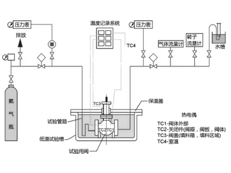
A conventional three-piece cryogenic ball valve is mainly composed of core components such as left valve body, middle body, right valve body, ball, left valve seat assembly and right valve seat assembly, with its structure shown in Figure 1.
2.2 Characteristics of Conventional Three-Piece Cryogenic Ball Valves
This type of three piece cryogenic temperature ball valve features simple operation. In the machining process, both the left and right valve bodies can be independently machined and polished on conventional CNC equipment, with low difficulty in the processing of parts. During assembly, each part is installed into the valve seat pocket from the side in sequence. In the factory test, only two blind flanges and fasteners are needed to complete the required normal temperature test and cryogenic simulation test. From a purely technological perspective, the conventional three-piece cryogenic ball valve is an ideal cryogenic pipeline shut-off valve. However, in actual use, its market share is rather small due to the inability to realize on-line maintenance.
2.3 Disadvantages of Conventional Three-Piece Cryogenic Ball Valves
The main disadvantages of this valve are multiple leakage points and the inability to achieve on-line disassembly, assembly and maintenance. When the three-piece low-temperature ball valve is connected by flanges, the flange end may leak due to fastener loosening, gasket failure, and uneven flange temperature caused by LNG gas-liquid phase separation [5]. Given the physical characteristics of LNG being flammable and explosive, the harm caused by external leakage is immeasurable. When welded connection is adopted, the entire valve can only be cut off from the pipeline for disassembly, analysis and maintenance, which is not allowed during pipeline operation. Therefore, three-piece cryogenic ball valves are generally not selected by owners and design institutes for LNG pipelines.
3 Structural Design of Common Top-Entry Ball Valves
3.1 Main Components
A common top-entry ball valve is mainly composed of valve body, left and right valve seats, ball, sealing ring, retainer ring, threaded sleeve, spring seat and fixing seat, with its structural design shown in Figure 2.
3.2 Characteristics of Top Entry Ball Valves
Top-entry ball valves are currently the most widely used type of cryogenic valves in LNG receiving terminals, mainly selected for their theoretical support for on-line maintenance [6]. Compared with the three-piece structure, after internal leakage occurs in the top-entry ball valve, the upper cover can be opened to check the leakage point and analyze the cause of leakage, providing a technical basis for subsequent part maintenance or replacement [7].
3.3 Disadvantages of Top Entry Ball Valves
The disadvantages of this valve are mainly concentrated in four aspects: structure, processing technology, on line maintenance and economy.
(1) Complex valve structural design. It can be seen from Figure 2 that the top-entry ball valve has more internal parts than the three-piece ball valve in terms of structure, and all parts need to be installed through the middle flange with a certain priority sequence for front and rear parts, placing high requirements on assembly skills. The valve needs to reserve a valve seat retraction stroke in design to facilitate the smooth installation of the ball into the valve cavity. This design will cause the lip seal to be repeatedly scratched by the crests of the surface roughness of the valve seat pocket during the retraction and reset of the valve seat [8], resulting in reduced sealing performance; small-diameter valves are limited by space, and some specifications can only adopt structures such as threaded sleeves. To prevent the synchronous rotation of the valve seat and the threaded sleeve, a separate anti-rotation structure needs to be designed, which makes the inner cavity structure extremely complex.
(2) Poor valve processability. The left and right valve seat pockets of the top-entry ball valve are both inside the cavity, so the tool bar needs to be custom-made and lengthened for processing. The longer tool bar causes a large vibration amplitude, so the feeding amount and rotating speed for processing are lower than conventional parameters, chatter marks often occur, and the precision is difficult to control [9], requiring multiple trimmings. After finish machining, it is difficult to carry out high-speed precision polishing. It is inconvenient to inspect the dimensions of the valve seat pocket during and after processing, and it is hard to accurately measure the dimensions and roughness. The top-entry ball valve has high requirements for the coaxiality of the two valve seat pockets, and this axis must also be perpendicular and intersecting with the axis of the middle flange. These processes need to be completed in one clamping to better ensure the position tolerance [10], which places high requirements on the performance of processing equipment.
(3) Difficult on-line valve maintenance. During on-line maintenance, the two ends of the valve are welded to the pipeline, and all operations can only be realized through the middle flange hole. Disassembly is extremely time-consuming and laborious due to the narrow remaining space in the valve cavity, which is a great test for after-sales service. In addition, what troubles users the most is that the maintenance effect of the top-entry ball valve cannot be verified immediately after on-line disassembly and maintenance, because the valve is welded to the pipeline and cannot be placed on a pressure test device for inspection [11], and the maintenance effect can only be verified by the pipeline medium pressure when the entire pipeline is restarted for the second time. However, many on-site maintenance cannot be guaranteed to pass smoothly at one time. If the maintenance fails, the entire process has to be repeated, resulting in incalculable time costs. In the actual use by users, the time for each shutdown and maintenance is very precious, and the rush repair is a race against time, which does not allow repeated disassembly and repair. Therefore, it is common for many valves on the pipeline to be used reluctantly even if a little internal leakage occurs [12].
(4) Poor valve economy. Due to structural reasons, the main parts of the top-entry ball valve can only be installed from the middle flange during assembly. Before the ball is installed into the valve cavity, the front and rear valve seat assemblies need to be retracted. Only when the distance between the end faces of the two valve seats is greater than the width of the ball port groove can the ball be smoothly installed into the valve cavity. A special additional tool is required to pull or expand the valve seat assemblies during their retraction [13]. Due to the high specificity and low versatility of the tools, the resulting additional cost accounts for a relatively large proportion, which is also one of the reasons why the market price of top-entry ball valves has remained high.
4 Structural Design of the New Type of On-Line Non-Destructive Disassembly and Assembly Wafer Ball Valve
4.1 Main Components
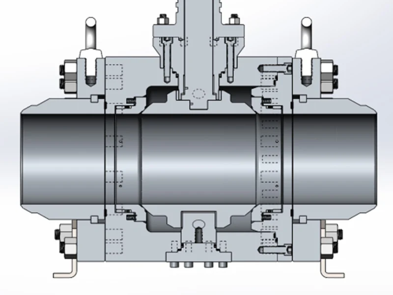
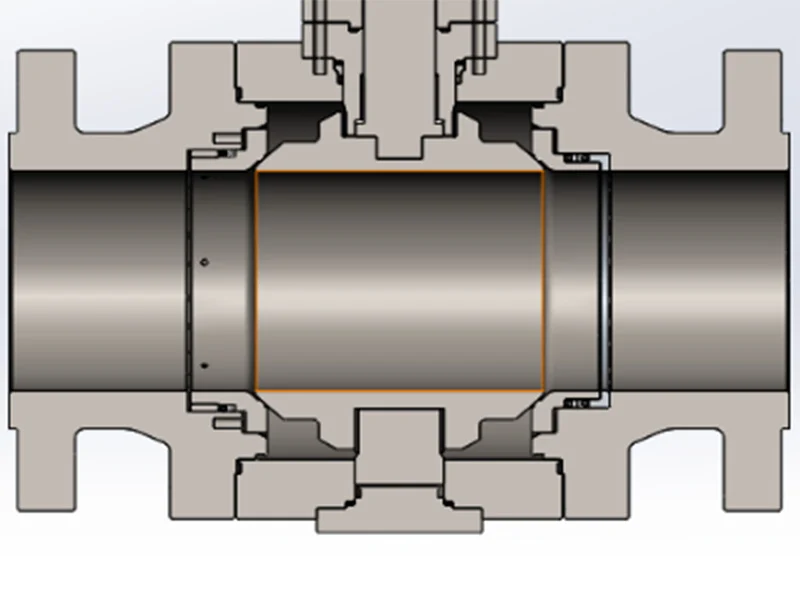
The new type of on-line non-destructive disassembly and assembly wafer ball valve is mainly composed of middle body, ball, left and right valve seat assemblies, valve seat end cover, fasteners, upper and lower shafts, four-piece split ring, as well as a sleeve or flange cover connected to the pipeline, as shown in Figure 3.
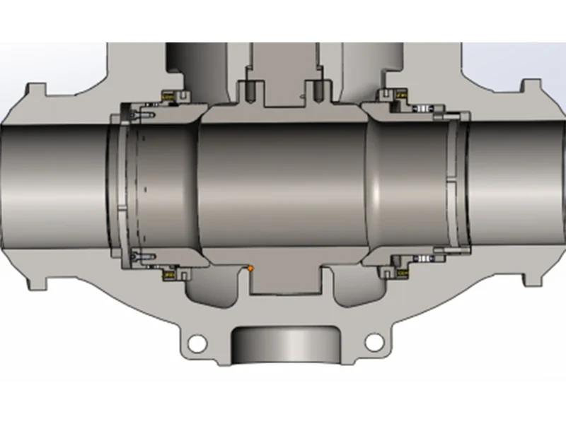
4.2 Characteristics of the On-Line Non-Destructive Disassembly and Assembly Wafer Ball Valve
The new type of on-line disassembly and assembly wafer ball valve features a modular design and is divided into a connection module and a detachable module. The connection module consists of a sleeve with a welding end, a loose flange and a four-piece split ring. The detachable module is composed of a middle body, a ball, left and right valve seat assemblies, a valve seat end cover, fasteners, and upper and lower shafts. One end of the connection module is welded to the pipeline, and the other end is bolted to the detachable module with fasteners, with a gasket used for sealing between the connection module and the detachable module.
During the assembly of the detachable module, the left valve seat assembly in Figure 3 is first directly installed into the left valve seat pocket, then the ball is installed, and then the right valve seat assembly is installed into the end cover valve seat pocket. The end cover is directly connected to the middle body with screws. At this time, the middle body, left and right valve seat assemblies, and end cover form a separate assembly through fasteners, which is referred to as the detachable module. Before the valve leaves the factory, the connection module and the detachable module are bolted together with fasteners, and only the welding end needs to be welded to the pipeline during construction [14]. During maintenance, the welding end does not need to be cut, and the detachable module can be taken out from the middle by loosening the fasteners to quickly replace the internal parts. This new structure not only retains the advantages of easy processing and assembly of the cryogenic three-piece ball valve, but also meets the needs of on-line maintenance, forming a new product by the perfect combination of the two.
4.3 Advantages of the On-Line Non-Destructive Disassembly and Assembly Wafer Ball Valve
The biggest advantage of this structure is its simplified design; all valve parts are circular, with uniform deformation at cryogenics and easy blank material selection. Secondly, it features simple processing technology. The valve seat pocket of the new structure is processed by turning, with a short and sturdy tool bar avoiding chatter marks, and the high-speed operation of the chuck improving turning efficiency. Micrometer detection is not limited by space, making measurement more accurate and convenient. No special tooling is required for the polishing process, and the roughness after precision polishing is easier to measure.
Thirdly, it is more convenient for assembly and maintenance. The installation and testing of the new structural wafer ball valve are basically the same as those of ordinary three-piece ball valves, with fast installation and convenient testing. When internal parts need to be replaced for valve maintenance, only the detachable module needs to be removed for part replacement, and the valve can be reinstalled on the pipeline after passing the test on a general pressure test device. This effectively solves the defect that the performance of the top-entry ball valve cannot be verified in a timely manner after maintenance.
The new structural wafer ball valve has good economic efficiency. The blank cost and processing cost are much lower than those of the top-entry ball valve, and the cost of special tooling and fixtures is also saved, providing great potential for enterprises to reduce costs and increase efficiency.
4.4 Disadvantages of the On-Line Non-Destructive Disassembly and Assembly Wafer Ball Valve
Every product has its disadvantages, and the new ball valve structure with on-line maintenance is no exception, mainly reflected in the following aspects: first, in order to realize on-line disassembly and assembly, the left and right bodies are split, resulting in more parts than the conventional three-piece ball valve, and the corresponding processes are more than those of the common three-piece ball valve. Secondly, there is one more external leakage point than the conventional wafer ball valve, i.e., the flange end cover. Compared with the top-entry ball valve, it also has more external leakage points, mainly at the middle flange and the bottom cover. Although there are theoretically more external leakage points, the sealing at these parts is static sealing, and durable and effective sealing can be easily achieved with generally no leakage problems, which is also one of the reasons why the new on-line maintenance ball valve is worthy of promotion.
5 Other Applications
Based on the above analysis, the structure, advantages and disadvantages of this new type of on-line maintenance ball valve are mainly introduced from the perspective of LNG application. However, in terms of structure, this structure is not limited to this application and is worthy of promotion in various pipelines that use welding ends to realize shut-off or flow regulation, especially for many important pipelines where owners have extremely short time limits for maintenance and cannot afford the time waste caused by returning the valve to the factory for maintenance. In such cases, the advantage of this structure in solving maintenance problems on site is prominent.
6 Conclusion
The structure of the new type of cryogenic on-line non-destructive disassembly and assembly wafer ball valve can be adjusted according to the actual needs of the pipeline in addition to the form introduced above. For example, in the processing of large diameter valves, if the valve seat part of the middle body is difficult to process due to depth, the left valve seat can be adjusted to the same structure as the right one; similarly, in terms of pipeline shut-off, this structure is applicable to both single-piston and double-piston types [15], and its service performance is not limited by the structure.
Compared with international advanced technologies, China’s cryogenic valve industry is still in the primary and intermediate stage, and product innovation is an inevitable path for us to move to a higher stage. Although this design form has not been widely applied in China, with its various prominent advantages, it is believed that it will soon be used in pipelines dominated by LNG. In the future, we will still take this as the foundation, accumulate rich technical experience through a large number of tests, explore more new breakthroughs, and strive to make due contributions to the technological development of China’s pipeline valves!
References
[1] Wei Pengfei, Yang Jiadong, Jia Zhen. A brief analysis of the development problems and trends of marine LNG[J]. Equipment Management and Maintenance, 2023, (14).
[2] BS6364, Valves for cryogenic services[S].
[3] API 6D, Specification for Pipeline and Piping Valves[S].
[4] Huang Huilong, Li Feng. Experience in handling high-pressure LNG flange leakage[J]. Small and Medium Enterprise Management and Technology (late issue), 2020, (04).
[5] Hao Weisha, Peng Lin, Cheng Honghui, et al. Common quality problems of pipeline ball valves from the perspective of supervision[J]. Fluid Machinery, 2014(2):53-56.
[6] Shi Xiaodong, Xu Yanhua, Jin Tiancheng. Structural design and optimization analysis of cryogenic top-mounted fixed inclined ball valve[J]. Valves, 2022, (03).
[7] Duan Dajun, He Wu, Li Songling.
[8] Lin Wanzhou, Yue Yunzhe, Luo Jixiong, et al. Analysis of the failure causes of quick-opening blind flange lip ring in raw gas filter separator [J]. Chemical Equipment and Pipeline, 2021, 58(01).
[9] Ren Heng. Research on deep hole machining technology in machining [J]. Paper Equipment and Materials, 2023, 52(04).
[10] Chen Shangshu, Lin Chen. Design of fixture for ball valve body machining center [J]. Valves, 2017, (06).
[11] API 598, Valve Inspection and Testing [S].
[12] Bai Tao, E Zhipeng, Cao Jia, et al. Exploration of problems in valve quality inspection [J]. China Petroleum and Chemical Standards and Quality, 2021, 41(19):57-58.
[13] Cong Lin, Zhong Yi. Ergonomic Design of Pneumatic Tools. Pneumatic Tools for Rock Drilling Machinery. 2020, (03).
[14] ASME B16.25, Buttwelding Ends[S].
[15] Wu Jun. Sealing Structure and Directional Analysis of DBB and DIB Type Fixed Ball Valves[J]. Chemical Equipment and Piping, 2016, 53(05):77-82.
(Received: 2023-10-23)